 |
Western Electric Touch Tone
Sewing Machine -
Automatic Answering Service
"Mirrophone" wire ribbon recorder/player
Telephones -
PicturePhone
- Bell Chime
Touch Tone Dialing - A
short video clip (32 seconds) from the 1962 Seattle World's Fair Bell System
movie called "Calling Century 21". Introduction to the new Touch Tone dialing
technology allows customers to push buttons on their phones instead of rotating
a dial wheel.
To view the official announcement by
Bell Labs in March of 1964 of this new technology, click
HERE.

We Offer Personalized One-On-One
Service!
Call Us Today at (651) 787-DIAL (3425)

Technical Information on the
DTMF (Dual-Tone Multi-Frequency) tones:
Standard
Touch-Tone (DTMF) Dial (key pad)
To hear each tone pair, click mouse
on
any of the 16 buttons on the "touch- tone dial" above. To hear a single
frequency tone (which occurs on some dials when pressing two adjacent row or column
buttons at the same time such as 5 and 8 or 2 and 3, click on the frequency number
label
in drawing. |
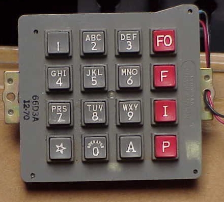
Type 66 Autovon Dial
(Click
HERE
for details)
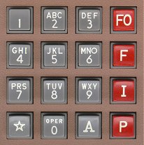
Autovon legends:
FO = Flash Override
F = Flash
I = Immediate
P = Priority
|

WEco Autovon dial |
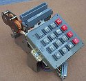
WEco Autovon dial
with card dialer |
Click the thumbnail images above to view
photos of Western Electric Autovon
dials. |
Each Touch-Tone digit is represented by a unique pair of
tones as shown in left image above. One tone from the low tone group (represented by the
blue lines and blue frequency numbers), and one tone from the high tone group (represented
by the red lines and red frequency numbers), are mixed together to form a "Dual-Tone
Multi-Frequency" signal.
Type 66 Autovon Dial (shown
at top of this page; right image):
[Photo and button designations above are the courtesy of
Stephen (Steph) Kerman]
- The Autovon legends are:
- FO = Flash Override
- F = Flash
- I = Immediate
- P = Priority
- AUTOVON - History and description -
From http://public.afca.scott.af.mil/
(link was dead when last checked):
A major development in long-haul communications in the
early 1960s was the Automatic Voice Network, commonly called AUTOVON. Activated in
December 1963, AUTOVON, derived from the Army’s Switched Circuit Automatic Network,
was designed to provide the Department of Defense with an internal telephone capability to
replace toll and Wide Area Telephone Service (WATS) calls, while also allowing precedence
preemption for high priority users. Development of the AUTOVON system represented one of
the most significant and comprehensive telecommunications programs ever undertaken by the
DOD. While the dedicated circuits used in earlier networks provided good response time,
weaknesses in survivability and reliability were significant problems. The loss of a
single circuit between two points disrupted communications between subscribers, and each
termination placed on the dedicated circuit required a separate instrument. AUTOVON did
much to correct these deficiencies.
AUTOVON became the principal long-haul, nonsecure voice
communications network within the Defense Communications System. The network served the
entire Department of Defense and handled essential communications concerning command,
operations, and administration. It was a global network comprised of interconnected
automatic switching centers and thousands of subscriber terminals throughout the world.
Over the next 25 years, the network would be continually modernized and expanded to
provide more service and capabilities to the users. Finally, it became a part of the new
Defense Switched Network (DSN), the replacement system activated in 1990 to provide
long-distance telephone service to the military.

If you are a technical history
buff, check out the Bell Labs Technical Journal article from 1960 on Touch-Tone
development! Click
HERE
to view it or
download it.
You must have Microsoft Word or OpenOffice.org to view this file.
You may also wonder about the human
factors history of the touch-tone dial button layout and design. Well,
I've got that answer for you too! Another Bell Labs Technical Journal
article from 1960 describes it in a document you can download by clicking
HERE.
(Thanks to Jodd Readick who donated hard copies for me to scan and convert to
electronic format.)
Also received the following information from a visitor to the website and
from a member of the TCI club:
"Regarding
your story on the original numbering layout for DTMF pads, I heard another story
that may or may not be true but I'll pass it along. The reason given to me for
not adopting a "ten-key" calculator (aka, adding machine) layout was that
ten-key users would dial so fast that it would trip up the decoders and result
in wrong numbers or incomplete calls. Reversing the order would slow those folks
down and rest of the world wouldn't care either way." - Bruce Robin
"A curious counterpoint to this corporate
history are the independent statements made to me by two members of the Bell
Telephone Laboratories staff at that time. One is a personal friend who is a
physicist that participated in the human factors design effort and the other was
one of the Noble prize recipients for the invention of the transistor. They both
reported to me that there was fear that some equipment couldn't keep up with
good adding machine layout inputers. Such admissions were conceivably not
included in the official corporate write-ups." - J. Marshall Reber
Some historical trivia -
"A pushbutton telephone that may eventually
replace the conventional [rotary] telephone dial is under development by
the Bell Telephone Laboratories. Instead of twirling a dial, users will
press numbered buttons to make a call - a faster process than dialing.
These new sets were placed on trial last summer [summer of 1959], then
taken out of service for study at the [Bell Telephone] Laboratories. Much
research and testing remains to be done before the sets can be made in quantity
and placed in service, but these may be the telephones of the future." -
Telephone Almanac for 1960, Southern Bell
Telephone and Telegraph Company/Bell Telephone System.
"In the
late 60’s and early 70’s the "#" symbol was standardized as a preface
to indicate that the call was to be a Picturephone (video) call. Picturephone service was
offered in a few markets (Chicago, NY) until it was killed about 1973. For business
callers with a multiline keyset (2565), the line lamp would change from a white light to a
red light (special polarity sensitive "dual-color" lamps) once the "#"
key was pressed." - Courtesy of Rick
Walsh.
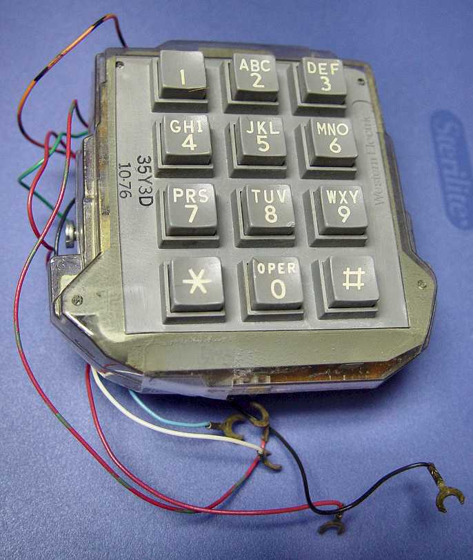
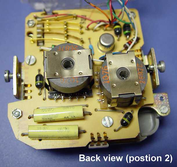
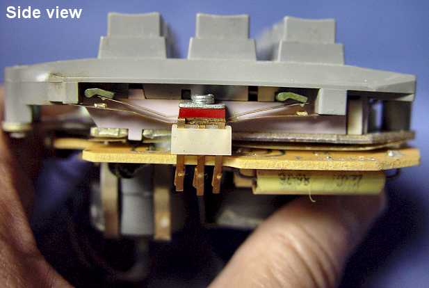
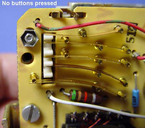
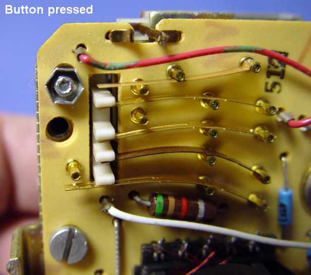
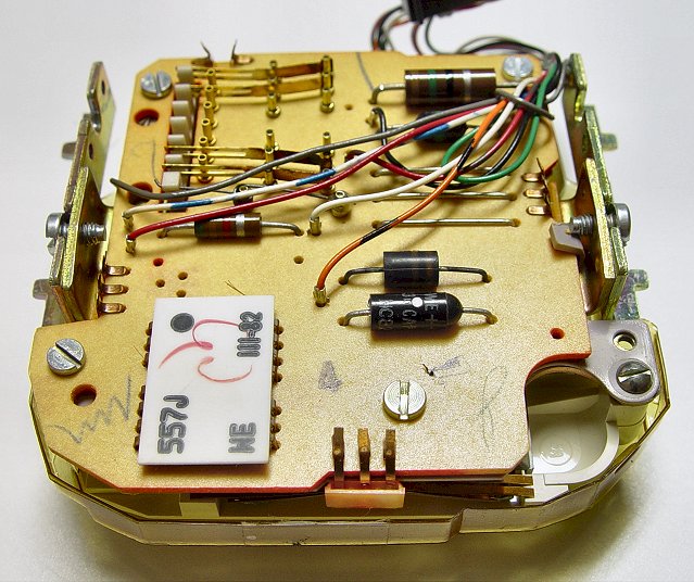
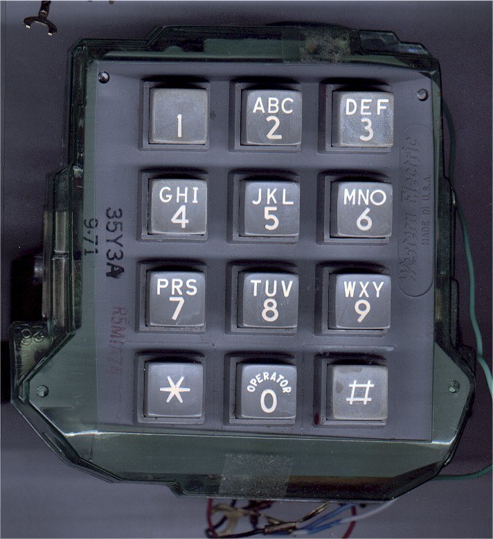
- Some photos of
the Western Electric type 35 series dial:
Front view
with dust cover installed
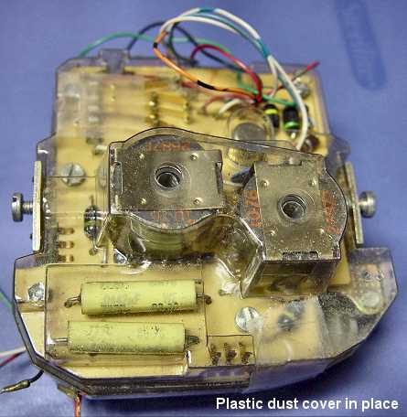
Rear view with dust cover installed
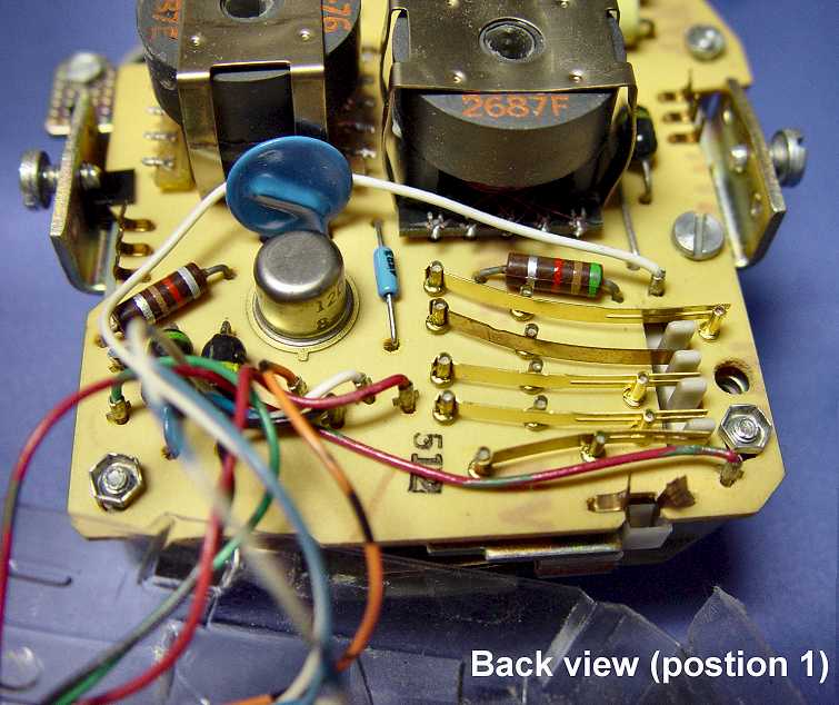
Rear view
showing switch assembly, inductors, varistors and transistor
Rear view
showing capacitors, other side of inductors and more varistors
Side view
showing switch contacts
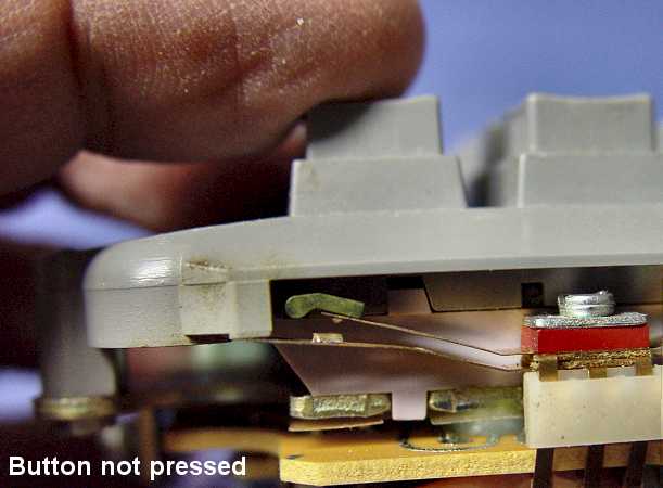
Buttons NOT pressed showing
switch - typical)
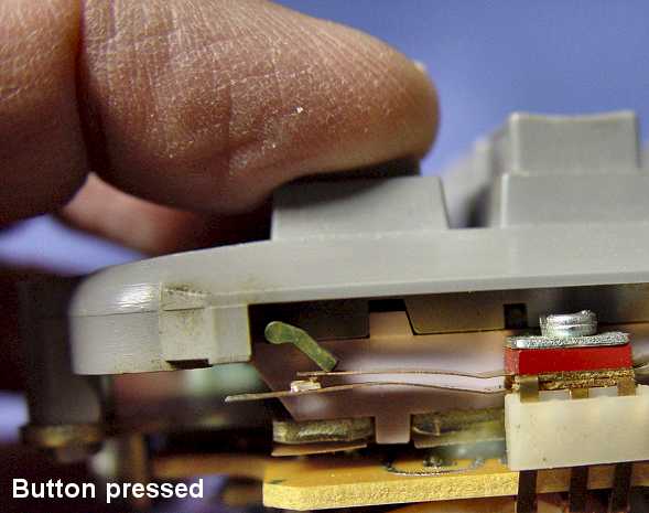
Button pressed (side switch - typical)
Buttons NOT pressed (rear switch assembly)
Button
pressed (rear switch assembly)
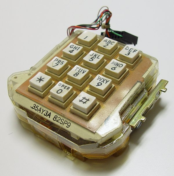
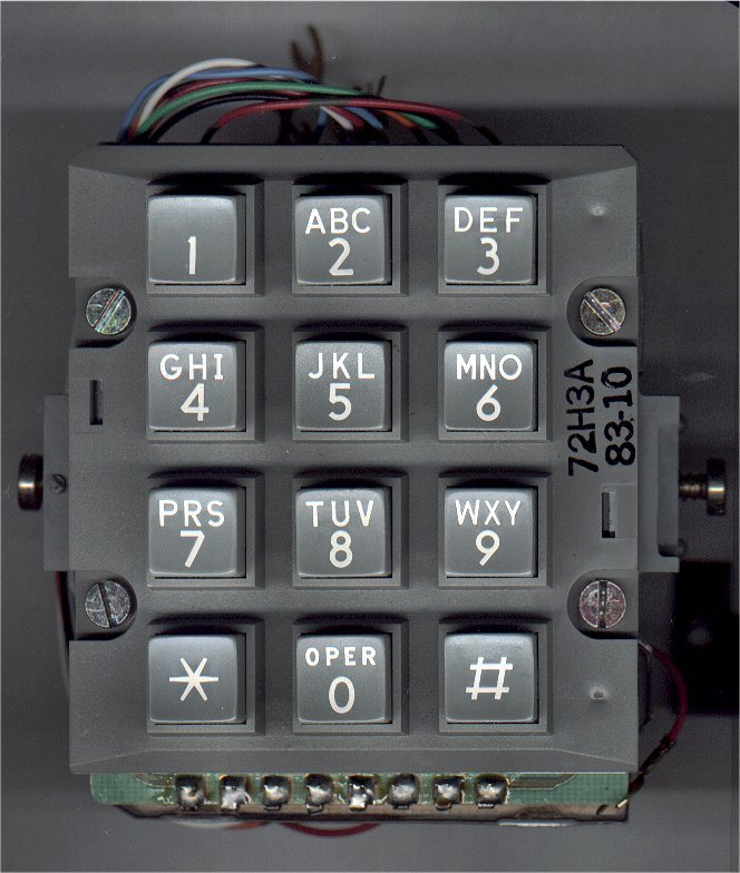
Here are two photos of a 35AY3A
(white-button 35 type touch-tone dial) that was part of the Western Electric
Com key 416 telephone:
Top
View
Bottom View
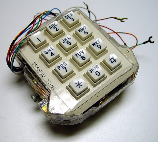
And a photo of a
35AH3D dial
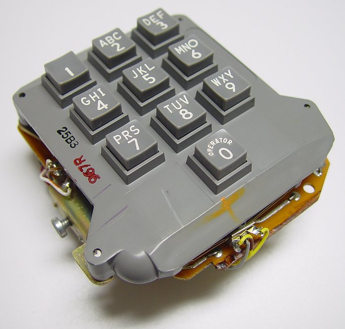
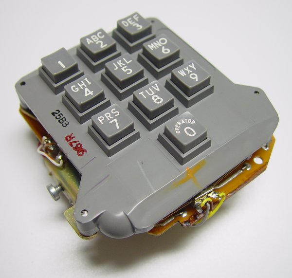
And finally, a couple photos of the 25B3 dial
used on the first touch-tones in common use (they only had ten buttons):
25B3-Photo1
25B3-Photo2.
A schematic for a 25P4 or 25W3 dial can be viewed
by clicking here.
>>> ATTENTION ELECTRONIC HOBBYIST and STUDENTS <<<
We get requests for DTMF (Touch-Tone) decoder projects from students and hobbyist periodically.
Although we don't have a schematic and parts list for building a complete
project, we did find two manufactures of DTMF decoder integrated circuits
that can be the basis of this project. Download the PDF data files by
clicking on the following links:
Motorola MC145436A - a 14 pin chip
HOLTEK HT9170 - Available from
Digikey for under $3.00 (USA) |
To view schematics and information
on the
Touch-Tone dials used in Western Electric phones,click on the two links below:
In order for the central-office
receiver to register the digit properly, the tone-address signals must meet the following
requirements:
1) Signal Levels:
Nominal level per frequency: -6 to -4 dBm. Minimum level per frequency: Low Group, -10
dBm; High Group, -8 dBm. Maximum level per frequency pair: +2 dBm. Maximum difference in
levels between frequencies: 4 dB.
2) Frequency Deviation: +/- 1.5 percent of the values given above.
3) Extraneous frequency components: The total power of all extraneous
frequencies accompanying the signal should be a t least 20 dB below the signal power, in
the voice band above 500 Hz.
4) Voice Suppression: Voice energy from any source should be suppressed
at least 45 dB during tone signal transmission. In the case of automatic dialing, the
suppression should be maintained continuously until pulsing is completed.
5) Rise Time: Each of the two frequencies of the signal should attain at
least 90 percent of full amplitude within 5 ms, and preferably within 3 ms for automatic
dialers, from the time that the first frequency begins.
6) Pulsing Rate: Minimum duration of two-frequency tone signal: 50 ms
normally; 90 ms if transmitted by radio. Minimum inter-digital time: 45 ms.
7) Tone leak during signal off time should be less than -55 dBm.
8) Transient Voltages: Peak transient voltages generated during tone
signaling should be no greater than 12 dB above the zero-to-peak voltage of the composite
two-frequency tone signal.
|

